
Section 1:
The first section of this circuit controls the waist motor and is supposed to control the phototrophic behavior <<WRONG!!!.
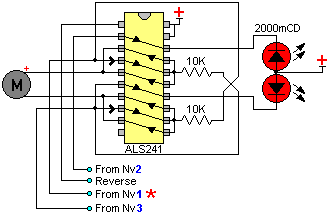
This section works with the 74ALS241 IC. It is a Tri-State nonInverting buffer. Nv1 has an * because I want to point out that the LEDs output is conected only to Nv3 ( Just look the circuit below, it explains it better).
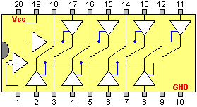
74ALS241
In case you have no idea about the 74ALS241 pins...
Circuit:
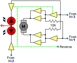
The circuit is pretty simple, two signals are sent from Nv1 and Nv3 to control the waist motor. When the reverse sensor is activated, the enable goes LOW and the signal is swaped (swapt, swap, I need better english...) between the buffers and the resistors. In other words: When the buffers are active, the resistance stops the signal from interfering, but when they are disabled, the signal is able to pass trough the resistors, reversing the motor. It also has 2 LEDs connected to the outputs of Nv3 and Nv2. This LEDs are NOT used as light sensors!!! ( I thought they did...). Instead, they are used for a much more simple task: To indicate when the bot is in ''reverse state''. They are just BLINKIN' LIGHTS!!! New: Viewing the Walkman video from Solarbotics I learned that the LEDs are also used to detect nearby objects. The reflected light is picked up by the light sensors and the bot avoids them while reversing.