
| Solar Engines | Pummers | PhotoVores | Heads | Walkers | Other |
|
P5v2 Circuit Operation |
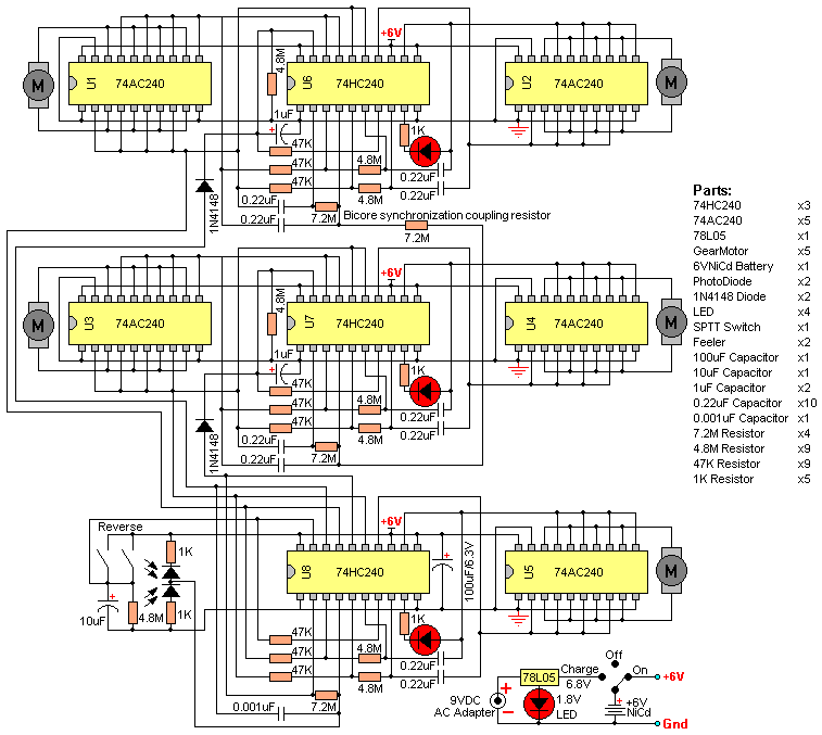 |
Here is a description of the P5v2-Walker circuit operation.

Understanding how this electronic circuit works should help
you with troubleshooting other bicore walkers as well. AN OVERVIEW OF THE P5v2 WALKER ELECTRONICS by Wilf Rigter - Feb 2001 The P5 design uses only eight 74HC/AC240 chips which are all octal inverting buffers. Each 74HC/AC240 chip has two groups of four inverters each controlled by a tri-state enable pin (pin 1 and 19). The 74AC240 chips (U1-U5) are used as h-bridge style motordrivers since they have almost double the drive current compared to 74HC240 chips. These motor driver chips are permanently enabled by grounding control pins 1 and 19. The two groups each have four inputs connected in common to a bicore output and the four outputs are connected in common to one motor winding terminal. Since each bicore has two complementary outputs the voltage across the motor winding causes the motor to rotate back and forth. The 74HC240 chips U6 and U7 are each used to form a master-slave bicore pair with reverser. The inverters used for the bicores are permanently enabled by grounding pin 1. The inverters used for reversing are turned on or off with the tri-state enable pin 19. Only 2 of the 4 tristate inverters are used conventionally for reversing the phase of the slave bicores while the other two are put to a novel use: one inverter is used to provide positive feedback to the enable pin and the second spare inverter is used to turn on a RED flashing LED when the reverser is active. The flashing LED also provides diagnostic visual indication of the operation of the slave bicore. The 74HC240 chip used for U8 provides a reverser and a slave bicore for the waist motor as well as a monocore (aka High Low Oscillator) photobridge comparator which controls the phasing of the front and rear motors. I) The photobridge comparator uses 2 inverters from U8 connected in series as an voltage controlled oscillator with complementary outputs to generate three states : a. high/low outputs b. low/high outputs c. both outputs to oscillate. a. if the left PD gets more light than the right PD, the two inverter complementary outputs are steady state dc. The inverter with the low output reverses the left slave bicore and corresponding rear leg causing the walker to turn left. b. if the right PD gets more light than the left PD, the two inverter complementary outputs are steady state dc (opposite to a.) The inverter with the low output "reverses" the right slave bicore causing the walker to turn right. c. if both PD get equal light, the two inverter complementary outputs are pulsing and neither of the slave bicores is reversed causing the walker to go straight. II) Two master suspended bicores in U5 and 6 are coupled at their inputs with a 7.2M phase sync resistor so that they will oscillate in quadrature with their waveforms overlapping by 25%. These waveforms are connected to the 74AC240 motor driver which control the front legs. III) Two rear motor slave bicores use inverters from U5 an U6 with timing components that delay the slave bicore output by about 25%. These are connected to the front leg motor drivers (6 inverters for each motor). IV) Two inverters in U6 and U7 are used for signal reversing and are connected between the outputs of each of the master bicores (front legs) and the slave bicores (rear legs) to control turning with enable signals from the photo comparator circuit. When the light is balanced pin 19 of U6 and U7 are both high, both reversers are turned off, the tristate inverters are disabled and the walker moves straight. V) The waist slave bicore circuit in U8 uses 2 inverters to control the waist motor driver. VI) The waist reverser uses two inverters in U8 and is connected between one output of each of the U6 and U7 master bicores and the waist slave bicore circuit inputs described in V). The waist motor phase reversal occurs when one of two tactile switches is triggered by collision with an obstacle. At that time the U8 tristate inverters are enabled. VII) The power supply consists of a 6V NiCd battery and charger circuit with a three position switch for on-off and charging. A 78L05 is included for recharging a 900mAHr battery pack at 0.1C without removing it from the walker. DETAILS OF OPERATION The Photo Comparator The photo comparator uses two photodiodes as a "photo bridge" to sense when the light level on the left and right PDs is balanced or unbalanced. Two optional resistors are connected in series with the PD to limit current in bright light and prevent PD destruction in case of a wrong connection during assembly and testing. The two photodiodes must be connected reverse biased in series across the power supply with the midpoint acting as a voltage divider. It uses 2 inverters in U8 connected in series as a High / Low / Oscillate (HLO) circuit to give complimentary steady state outputs when the PDs are unbalanced. Both inverter outputs will oscillate when the light on the PDs is balanced and the photo bridge midpoint voltage is near the switching threshold of the first inverter input. A small cap (0.001uf) connected from the output of the second inverter back to the midpoint of the PD bridge provides positive feedback for oscillation and reduces frequency and power consumption. The ouputs of the HLO are connected through diodes to discharge capacitors on the tristate enable (pin 19) of the reverser circuits in U6 and U7. The capacitors remain discharged as long as the HLO output is pulsing or steady state high. The value of the cap/resistor on U6/7 pin 19 scan be adjusted if required to give a faster or slower response to differential light change. When the photo bridge is unbalanced, the midpoint voltage of the bridge stops the HLO oscillation. One HLO output then goes low steady state and a capacitor at the corresponding reverser tristate input (pin 19) discharges through the parallel resistor until the threshold is reached enabling the turning reverser. Note that one of the controlled inverters outputs is connected through a resistor to pin 19 for positive feedback to quickly discharge the cap when crossing the threshold to provide a snap action in the reverser operation. A second inverter is used to connect a red LED to one slave bicore ouput. The Master Bicores The master bicores generate the two sets of central pattern signals which are phase locked in quadrature with synchronization coupling resistor. Interestingly, this method of phase locking relies on the fact that normally both bicores are oscillating at nearly the same frequency but with one slightly faster than the other. This faster bicore will "pull" the frequency of the slower bicore and effectively "enslave" that master bicore. However with perfectly matched components and the two could switch roles and while frequency locked, they would wander back and forth in phase relationship! The Reversers The reversers are sometimes called Mat Muxes and their function is to control the phase inversion of pairs of signals. This is done by routing the signals through one of two parallel paths: a) inverted signal through a tristate inverter or b) non-inverted signal through a resistor when the tristate inverter is disabled. For U6 and U7 the complementary outputs from the master bicore connects to the reverser which when enabled by PD comparator is used to add 180 degree phase shift to the signal from the master to the slave bicore and subsequently, shifts the front and rear legs rotations phasing by 180 degrees. Note that the waist reverser in U8 uses one output each from the two master bicores and when enabled by collision switches, changes the phase angle of the waist rotation. The Slave Bicores The slave bicores delay the phase angle of the front legs with respect to the rear legs which are controlled by the master bicores. The reversers between the master and slave bicores determine whether the front and rear legs (on opposite corners) are moving in the same or opposite direction when the legs are on the ground. This causes the legs to both move forwards or backwards together or to rotate the body of the walker slightly with each step of those legs until the light level is balanced on the two PDs. The operation of the reversers and the slave bicore is indicated with flashing red LED when the reverser inverters are enabled. The Motors and Legs Five motors are used to control rotation of each of the four legs and the waist. The leg motors are mounted nearly vertically with an L shaped reciprocating legs swinging in an arc front to rear. Only two legs are pushing against the floor at one time. The reciprocating waist motor is mounted horizontally raising one pair of legs in the air while the other pair of legs are lowered on the floor. Depending on the phase angle of the waist motor, the legs are lowered on the floor on the front or the rear stroke of the legs and therefore determines the forward and reverse direction. When a turning reverser is active, one set of diagonal legs moves forward or backwards while the other set rotates the walker clockwise or counter-clockwise around it's center. The net effect of this is a sweeping turn motion. The 74AC240 motor driver chips (U1-U5) can be used to control small efficient gear motors such as converted hobby servos or camcorder/LCD projector lens motors. Gear ratios of 40-100 provide the right combination of torque and RPM. The maximum current at 6V should be less than 150ma to avoid overheating the motor driver chips. If desired the 74AC240s can be replaced with five higher current h-bridges or five DPDT relays. The Power Supply The last part is the power supply which consists of a 6V NiCd battery pack and a charger circuit designed to be used with a wall type AC adapter. A switch is included to turn the walker on or off or to connect the battery to the charger circuit. The 78L05 provides constant current charging until the maximum float voltage is reached. A red LED in in series with the 5V regulator ground reference raises the output voltage to the 6.8V float voltage required for a 6V NiCd battery and also indicates when the AC adapter power is ON. The 78L05 limits the current to 100ma with thermal shutdown in case of an overload to ground. This current is meant to charge a battery at a safe 0.1C rate and therefore must be used with a 6V NiCd battery with at least 900mAhr capacity. Red LEDs have varying (1.6V-2.0V) forward voltage drops and the red LED for this application should be efficient and selected for a 1.8V drop to set the charge open circuit output voltage to 6.8V. Enjoy, Wilf |
| Solar Engines | Pummers | PhotoVores | Heads | Walkers | Other |